
Geometry shaders
So far we've used vertex and fragment shaders to manipulate our input vertices into pixels on the screen. Since OpenGL 3.2 there is a third optional type of shader that sits between the vertex and fragment shaders, known as the geometry shader. This shader has the unique ability to create new geometry on the fly using the output of the vertex shader as input.
Since we've neglected the kitten from the previous chapters for too long, it ran off to a new home. This gives us a good opportunity to start fresh. At the end of this chapter, we'll have the following demo:
That doesn't look all that exciting... until you consider that the result above was produced with a single draw call:
glDrawArrays(GL_POINTS, 0, 4);
Note that everything geometry shaders can do can be accomplished in other ways, but their ability to generate geometry from a small amount of input data allows you to reduce CPU -> GPU bandwidth usage.
Setup
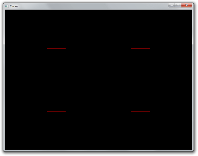
Let's start by writing some simple code that just draws 4 red points to the screen.
// Vertex shader
const char* vertexShaderSrc = R"glsl(
    #version 150 core
    in vec2 pos;

    void main()
    {
        gl_Position = vec4(pos, 0.0, 1.0);
    }
)glsl";

// Fragment shader
const char* fragmentShaderSrc = R"glsl(
    #version 150 core
    out vec4 outColor;

    void main()
    {
        outColor = vec4(1.0, 0.0, 0.0, 1.0);
    }
)glsl";
We'll start by declaring two very simple vertex and fragment shaders at the top of the file. The vertex shader simply forwards the position attribute of each point and the fragment shader always outputs red. Nothing special there.
Let's also add a helper function to create and compile a shader:
GLuint createShader(GLenum type, const GLchar* src) {
    GLuint shader = glCreateShader(type);
    glShaderSource(shader, 1, &src, nullptr);
    glCompileShader(shader);
    return shader;
}
In the main function, create a window and OpenGL context with a library
of choice and initialize GLEW. The shaders and compiled and activated:
GLuint vertexShader = createShader(GL_VERTEX_SHADER, vertexShaderSrc);
GLuint fragmentShader = createShader(GL_FRAGMENT_SHADER, fragmentShaderSrc);

GLuint shaderProgram = glCreateProgram();
glAttachShader(shaderProgram, vertexShader);
glAttachShader(shaderProgram, fragmentShader);
glLinkProgram(shaderProgram);
glUseProgram(shaderProgram);
After that, create a buffer that holds the coordinates of the points:
GLuint vbo;
glGenBuffers(1, &vbo);

float points[] = {
    -0.45f,  0.45f,
     0.45f,  0.45f,
     0.45f, -0.45f,
    -0.45f, -0.45f,
};

glBindBuffer(GL_ARRAY_BUFFER, vbo);
glBufferData(GL_ARRAY_BUFFER, sizeof(points), points, GL_STATIC_DRAW);
We have 4 points here, each with x and y device coordinates. Remember that device coordinates range from -1 to 1 from left to right and bottom to top of the screen, so each corner will have a point.
Then create a VAO and set the vertex format specification:
// Create VAO
GLuint vao;
glGenVertexArrays(1, &vao);
glBindVertexArray(vao);

// Specify layout of point data
GLint posAttrib = glGetAttribLocation(shaderProgram, "pos");
glEnableVertexAttribArray(posAttrib);
glVertexAttribPointer(posAttrib, 2, GL_FLOAT, GL_FALSE, 0, 0);
And finally the render loop:
glClearColor(0.0f, 0.0f, 0.0f, 1.0f);
glClear(GL_COLOR_BUFFER_BIT);

glDrawArrays(GL_POINTS, 0, 4);
With this code, you should now see 4 red points on a black background as shown below:

If you are having problems, have a look at the reference source code.
Basic geometry shader
To understand how a geometry shader works, let's look at an example:
#version 150 core

layout(points) in;
layout(line_strip, max_vertices = 2) out;

void main()
{
    gl_Position = gl_in[0].gl_Position + vec4(-0.1, 0.0, 0.0, 0.0);
    EmitVertex();

    gl_Position = gl_in[0].gl_Position + vec4(0.1, 0.0, 0.0, 0.0);
    EmitVertex();

    EndPrimitive();
}
Input types
Whereas a vertex shader processes vertices and a fragment shader processes fragments, a geometry shader processes entire primitives. The first line describes what kind of primitives our shader should process.
layout(points) in;
The available types are listed below, along with their equivalent drawing command types:
- points - GL_POINTS (1 vertex)
- lines - GL_LINES, GL_LINE_STRIP, GL_LINE_LIST (2 vertices)
- lines_adjacency - GL_LINES_ADJACENCY, GL_LINE_STRIP_ADJACENCY (4 vertices)
- triangles - GL_TRIANGLES, GL_TRIANGLE_STRIP, GL_TRIANGLE_FAN (3 vertices)
- triangles_adjacency - GL_TRIANGLES_ADJACENCY, GL_TRIANGLE_STRIP_ADJACENCY (6 vertices)
Since we're drawing GL_POINTS, the points type is appropriate.
Output types
The next line describes the output of the shader. What's interesting about geometry shaders is that they can output an entirely different type of geometry and the number of generated primitives can even vary!
layout(line_strip, max_vertices = 2) out;
The second line specifies the output type and the maximum amount of vertices it
can pass on. This is the maximum amount for the shader invocation, not for a
single primitive (line_strip in this case).
The following output types are available:
- points
- line_strip
- triangle_strip
These types seem somewhat restricted, but if you think about it, these types are sufficient to cover all possible types of primitives. For example, a triangle_strip with only 3 vertices is equivalent to a regular triangle.
Vertex input
The gl_Position, as set in the vertex shader, can be accessed using the
gl_in array in the geometry shader. It is an array of structs that looks like
this:
in gl_PerVertex
{
    vec4 gl_Position;
    float gl_PointSize;
    float gl_ClipDistance[];
} gl_in[];
Notice that vertex attributes like pos and color are not included, we'll
look into accessing those later.
Vertex output
The geometry shader program can call two special functions to generate
primitives, EmitVertex and EndPrimitive. Each time the program calls
EmitVertex, a vertex is added to the current primitive. When all vertices have
been added, the program calls EndPrimitive to generate the primitive.
void main()
{
    gl_Position = gl_in[0].gl_Position + vec4(-0.1, 0.0, 0.0, 0.0);
    EmitVertex();

    gl_Position = gl_in[0].gl_Position + vec4(0.1, 0.0, 0.0, 0.0);
    EmitVertex();

    EndPrimitive();
}
Before calling EmitVertex, the attributes of the vertex should be assigned to
variables like gl_Position, just like in the vertex shader. We'll look at
setting attributes like color for the fragment shader later.
Now that you know the meaning of every line, can you explain what this geometric shader does?
It creates a single horizontal line for each point coordinate passed to it.
Creating a geometry shader
There's not much to explain, geometry shaders are created and activated in exactly the same way as other types of shaders. Let's add a geometry shader to our 4 point sample that doesn't do anything yet.
const char* geometryShaderSrc = R"glsl(
    #version 150 core

    layout(points) in;
    layout(points, max_vertices = 1) out;

    void main()
    {
        gl_Position = gl_in[0].gl_Position;
        EmitVertex();
        EndPrimitive();
    }
)glsl";
This geometry shader should be fairly straightforward. For each input point, it generates one equivalent output point. This is the minimum amount of code necessary to still display the points on the screen.
With the helper function, creating a geometry shader is easy:
GLuint geometryShader = createShader(GL_GEOMETRY_SHADER, geometryShaderSrc);
There's nothing special about attaching it to the shader program either:
glAttachShader(shaderProgram, geometryShader);
When you run the program now, it should still display the points as before. You
can verify that the geometry shader is now doing its work by removing the code
from its main function. You'll see that no points are being drawn anymore,
because none are being generated!
Now, try replacing the geometry shader code with the line strip generating code from the previous section:
#version 150 core

layout(points) in;
layout(line_strip, max_vertices = 2) out;

void main()
{
    gl_Position = gl_in[0].gl_Position + vec4(-0.1, 0.0, 0.0, 0.0);
    EmitVertex();

    gl_Position = gl_in[0].gl_Position + vec4(0.1, 0.0, 0.0, 0.0);
    EmitVertex();

    EndPrimitive();
}
Even though we've made no changes to our draw call, the GPU is suddenly drawing tiny lines instead of points!
Try experimenting a bit to get a feel for it. For example, try outputting
rectangles by using triangle_strip.
Geometry shaders and vertex attributes
Let's add some variation to the lines that are being drawn by allowing each of them to have a unique color. By adding a color input variable to the vertex shader, we can specify a color per vertex and thus per generated line.
#version 150 core

in vec2 pos;
in vec3 color;

out vec3 vColor; // Output to geometry (or fragment) shader

void main()
{
    gl_Position = vec4(pos, 0.0, 1.0);
    vColor = color;
}
Update the vertex specification in the program code:
GLint posAttrib = glGetAttribLocation(shaderProgram, "pos");
glEnableVertexAttribArray(posAttrib);
glVertexAttribPointer(posAttrib, 2, GL_FLOAT, GL_FALSE, 5 * sizeof(float), 0);

GLint colAttrib = glGetAttribLocation(shaderProgram, "color");
glEnableVertexAttribArray(colAttrib);
glVertexAttribPointer(colAttrib, 3, GL_FLOAT, GL_FALSE,
                       5 * sizeof(float), (void*) (2 * sizeof(float)));
And update the point data to include an RGB color per point:
float points[] = {
    -0.45f,  0.45f, 1.0f, 0.0f, 0.0f, // Red point
     0.45f,  0.45f, 0.0f, 1.0f, 0.0f, // Green point
     0.45f, -0.45f, 0.0f, 0.0f, 1.0f, // Blue point
    -0.45f, -0.45f, 1.0f, 1.0f, 0.0f, // Yellow point
};
Because the vertex shader is now not followed by a fragment shader, but a
geometry shader, we have to handle the vColor variable as input there.
#version 150 core

layout(points) in;
layout(line_strip, max_vertices = 2) out;

in vec3 vColor[]; // Output from vertex shader for each vertex

out vec3 fColor; // Output to fragment shader

void main()
{
    ...
You can see that it is very similar to how inputs are handled in the fragment shader. The only difference is that inputs must be arrays now, because the geometry shader can receive primitives with multiple vertices as input, each with its own attribute values.
Because the color needs to be passed further down to the fragment shader, we add
it as output of the geometry shader. We can now assign values to it, just like
we did earlier with gl_Position.
void main()
{
    fColor = vColor[0]; // Point has only one vertex

    gl_Position = gl_in[0].gl_Position + vec4(-0.1, 0.1, 0.0, 0.0);
    EmitVertex();

    gl_Position = gl_in[0].gl_Position + vec4(0.1, 0.1, 0.0, 0.0);
    EmitVertex();

    EndPrimitive();
}
Whenever EmitVertex is called now, a vertex is emitted with the current value
of fColor as color attribute. We can now access that attribute in the fragment
shader:
#version 150 core

in vec3 fColor;

out vec4 outColor;

void main()
{
    outColor = vec4(fColor, 1.0);
}
So, when you specify an attribute for a vertex, it is first passed to the vertex shader as input. The vertex shader can then choose to output it to the geometry shader. And then the geometry shader can choose to further output it to the fragment shader.

However, this demo is not very interesting. We could easily replicate this behaviour by creating a vertex buffer with a single line and issuing a couple of draw calls with different colors and positions set with uniform variables.
Dynamically generating geometry
The real power of geometry shader lies in the ability to generate a varying amount of primitives, so let's create a demo that properly abuses this ability.
Let's say you're making a game where the world consists of circles. You could draw a single model of a circle and repeatedly draw it, but this approach is not ideal. If you're too close, these "circles" will look like ugly polygons and if you're too far away, your graphics card is wasting performance on rendering complexity you can't even see.
We can do better with geometry shaders! We can write a shader that generates the appropriate resolution circle based on run-time conditions. Let's first modify the geometry shader to draw a 10-sided polygon at each point. If you remember your trigonometry, it should be a piece of cake:
#version 150 core

layout(points) in;
layout(line_strip, max_vertices = 11) out;

in vec3 vColor[];
out vec3 fColor;

const float PI = 3.1415926;

void main()
{
    fColor = vColor[0];

    for (int i = 0; i <= 10; i++) {
        // Angle between each side in radians
        float ang = PI * 2.0 / 10.0 * i;

        // Offset from center of point (0.3 to accomodate for aspect ratio)
        vec4 offset = vec4(cos(ang) * 0.3, -sin(ang) * 0.4, 0.0, 0.0);
        gl_Position = gl_in[0].gl_Position + offset;

        EmitVertex();
    }

    EndPrimitive();
}
The first point is repeated to close the line loop, which is why 11 vertices are drawn. The result is as expected:

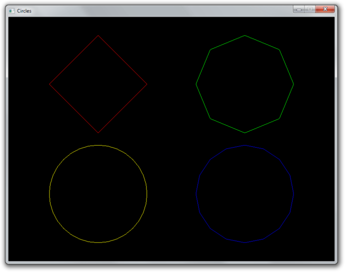
It is now trivial to add a vertex attribute to control the amount of sides. Add the new attribute to the data and to the specification:
float points[] = {
//  Coordinates  Color             Sides
    -0.45f,  0.45f, 1.0f, 0.0f, 0.0f,  4.0f,
     0.45f,  0.45f, 0.0f, 1.0f, 0.0f,  8.0f,
     0.45f, -0.45f, 0.0f, 0.0f, 1.0f, 16.0f,
    -0.45f, -0.45f, 1.0f, 1.0f, 0.0f, 32.0f
};

...

// Specify layout of point data
GLint posAttrib = glGetAttribLocation(shaderProgram, "pos");
glEnableVertexAttribArray(posAttrib);
glVertexAttribPointer(posAttrib, 2, GL_FLOAT, GL_FALSE,
                       6 * sizeof(float), 0);

GLint colAttrib = glGetAttribLocation(shaderProgram, "color");
glEnableVertexAttribArray(colAttrib);
glVertexAttribPointer(colAttrib, 3, GL_FLOAT, GL_FALSE,
                       6 * sizeof(float), (void*) (2 * sizeof(float)));

GLint sidesAttrib = glGetAttribLocation(shaderProgram, "sides");
glEnableVertexAttribArray(sidesAttrib);
glVertexAttribPointer(sidesAttrib, 1, GL_FLOAT, GL_FALSE,
                       6 * sizeof(float), (void*) (5 * sizeof(float)));
Alter the vertex shader to pass the value to the geometry shader:
#version 150 core

in vec2 pos;
in vec3 color;
in float sides;

out vec3 vColor;
out float vSides;

void main()
{
    gl_Position = vec4(pos, 0.0, 1.0);
    vColor = color;
    vSides = sides;
}
And use the variable in the geometry shader instead of the magic number of sides
10.0. It's also necessary to set an appropriate max_vertices value for our
input, otherwise the circles with more vertices will be cut off.
layout(line_strip, max_vertices = 64) out;

...

in float vSides[];

...

// Safe, floats can represent small integers exactly
for (int i = 0; i <= vSides[0]; i++) {
    // Angle between each side in radians
    float ang = PI * 2.0 / vSides[0] * i;

    ...
You can now create a circles with any amount of sides you desire by simply adding more points!
Without a geometry shader, we'd have to rebuild the entire vertex buffer whenever any of these circles have to change, now we can simply change the value of a vertex attribute. In a game setting, this attribute could be changed based on player distance as described above. You can find the full code here.
Conclusion
Granted, geometry shaders may not have as many real world use cases as things like framebuffers and textures have, but they can definitely help with creating content on the GPU as shown here.
If you need to repeat a single mesh many times, like a cube in a voxel game, you could create a geometry shader that generates cubes from points in a similar fashion. However, for these cases where each generated mesh is exactly the same, there are more efficient methods like instancing.
Lastly, with regards to portability, the latest WebGL and OpenGL ES standards do not yet support geometry shaders, so keep that in mind if you're considering the development of a mobile or web application.
Exercises
- Try using a geometry shader in a 3D scenario to create more complex meshes like cubes from points. (Solution)